Christmas disaster from Reid Phillips on Vimeo.
Gearbox design
So here's what I've been working on thr past two months.
I was in a group that decided to design an FNR (forward, neutral, reverse) transmission for an SAE Mini Baja car. Here's what the Wolfpack Motorsports SAE Baja racer looks like. We modeled ours off of their design. The FNR transmission would allow the vehicle, which currently only has a forwards gear, to stop, idle, and go into reverse while seated in the drivers seat.
The idea was to make the cheapest and lightest design (mainly because the Wolpack motorsports team doesn't think an FNR gearbox is necessary and it adds to the weight and cost of the car, and THEY'RE RIGHT)
Here was my first idea
-Super basic and clunky. We determined that the gear ratio would need to be 3:1 to get a healthy output speed of 45mph (including car/driver weight and friction factors).
Driven shaft is on the right, output is on the left. This was a 1:1 design, and we thought we could add on some miter gears later to get the correct ratio and angle. It is in the reverse setup as shown, the big spur gear turns the shaft and the smaller spur gears to give the shafts a different rotation. Those two big metal bars in the middle move up and down to allow for the different gears to mate. push the bar down once from the position it is in and you get neutral, push it once more and you get a forward gear.
*It is important to note that this design took us one and a half months to build. The next two ideas were made in 2 weeks.
Here's was my second design
I was in a group that decided to design an FNR (forward, neutral, reverse) transmission for an SAE Mini Baja car. Here's what the Wolfpack Motorsports SAE Baja racer looks like. We modeled ours off of their design. The FNR transmission would allow the vehicle, which currently only has a forwards gear, to stop, idle, and go into reverse while seated in the drivers seat.
The idea was to make the cheapest and lightest design (mainly because the Wolpack motorsports team doesn't think an FNR gearbox is necessary and it adds to the weight and cost of the car, and THEY'RE RIGHT)
Here was my first idea
 |
| Clunker FNR gearbox |
Driven shaft is on the right, output is on the left. This was a 1:1 design, and we thought we could add on some miter gears later to get the correct ratio and angle. It is in the reverse setup as shown, the big spur gear turns the shaft and the smaller spur gears to give the shafts a different rotation. Those two big metal bars in the middle move up and down to allow for the different gears to mate. push the bar down once from the position it is in and you get neutral, push it once more and you get a forward gear.
*It is important to note that this design took us one and a half months to build. The next two ideas were made in 2 weeks.
Here's was my second design
This one is a smaller (hard to tell) and has 11 gears, which means it weights a lot more. The ides was the same but bent with a curve and the miter gears were added. The idea is that the driven shaft on the back left turns and outputs to the right and turns another series of gears to create either forwards or reverse. Then the miter gears were added to get the ratio and the direction of the output we needed (We wanted the power to come in the left and out the bottom so it coulld enter a differential easy and out the the driveshafts, this meant the power had to make a 90 degree turn, and in come the miter gears!).
*it is important to note that this second design took 2 days to make before it was quickly scrapped for design 3.
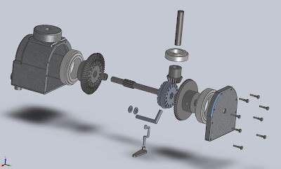
Here is that design:
 |
| Exploded view, it is upside down in relation to the images above |
Obviously this is the design we went with given the amount of detail. the 11 gears were traded for 3, with a simple shifting slidegear in between 2 large miter gears. All the gears in this assmebly run constantly but only one (or neither for neutral) are put to use in the output shaft.
*This design has come together over the past week and a half
Simple, light, EXPENSIVE. These gears are 2000 bucks a piece. I could get a new Jeep for the price of this gearbox, so we are still in the process of finding a cheaper vendor and considering machining our own gears.
Welcome to NCSU MAE.
Scarecrow Mask
There's something I've wanted to do for a long time, and I finally got around to doing it.
Making my own Scarecrow mask.
I used burlap and cotton matting as backing. I 3M spray-glued the cotton to the burlap, pressed, let dry until there were no more fumes, then cut out my pieces. I even went to an antique shop and found a foam head to work the whole thing around. It was sewn together with twine, brown thread, and black lace for the mouth portion.
I left a little burlap patch near the mouth to breathe out of with no cotton backing.
Black and White
This is a series using black ink.
 | |
| 5012 |
 | ||
| Screaming Baby in a Mozart Wig (inspired by SNL) |
 |
| Silhouette in Strokes |
 |
| #3 |
 |
| Washboard |
Mini city
So glad to be finally saying this but the minicity is COMPLETE!!
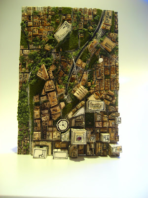
So the premise was to build a City in a bottle. I had received a Ship in a Bottle kit from a good friend and after building the kit in one work-less night I thought "I wonder if you could do this, but with a city" The way the ship "rose" in the bottle when the tieline was pulled was amazing, so i drew up some designs and started.
This is the base board. As you can see it folds up into a nice tight package which could be then unfolded and laid flat in the "bottle". I needed to get as much in the "bottle" as possible to build up a base. I say "bottle" because I had a couple laying around and just used an average of their diameter for my target. Not having a specific bottle in mind might have been my downfall...
The bottom of the base. Just electrical tape as a hinge on matte board. It worked very well.
This is the very beginning of the city layer. The terrain was cut into three strips and electrical tape hinged together. The first thing I built here was a stadium to be in the downtown area.
This is how the city layer folded, already it is showing to be very larger... much larger than the base layer when folded.
This is how the city layer would lay ontop of the base layer in the bottle. I tried a couple of buildings on hinges and tied them together but the room needed to lay them down compromised the space that would be left when they rose. I decided at this step to just glue the city layer permanently to the base layer. A decision that I stand behind for this model, and one that will most certainly lead to creation of an actual "City in a Bottle" in my future.
Work progressed to this stage...
To this one! finished model.
Assuming the average city block length is 0.075 miles (an average of NYC's 10 and 20 blocks per mile setup), the scale of this city is 1 to 9504.
Me and my city
The first rule of fight club is...
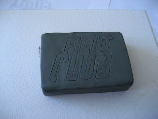
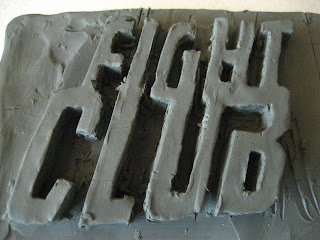
This is my soap prop.
pretty much what my workstation consisted of all last year, my TRUNK
They got more and more accurate the more I did, I know have 7, each with its own unique color.
pretty much what my workstation consisted of all last year, my TRUNK
They got more and more accurate the more I did, I know have 7, each with its own unique color.
Hammer test
This is a slip cast of the hammer mould. I slipped it 3 times to build up the cast, still got some really thin spots and some air bubbles, especially in the claw part of the hammer. This is a great example of using a slip cast to make me look super strong though
Hammer time
I'm going to try to say as little this time and let the pictures do the talking.
This is a hammer mould I made, same materials as the muffin.
The hammer was replaced and lots of release added.
Finally, many casts. The far left is a solid pigmentable plastic which I did not pigment. So it is translucent. Some of these didn't turn out too well still because of air bubbles. The yellow tint foam is a differnet weight than the white foam, but all are extremely light foam hammer casts.
Labels:
mould
Subscribe to:
Comments (Atom)


