I was in a group that decided to design an FNR (forward, neutral, reverse) transmission for an SAE Mini Baja car. Here's what the Wolfpack Motorsports SAE Baja racer looks like. We modeled ours off of their design. The FNR transmission would allow the vehicle, which currently only has a forwards gear, to stop, idle, and go into reverse while seated in the drivers seat.
The idea was to make the cheapest and lightest design (mainly because the Wolpack motorsports team doesn't think an FNR gearbox is necessary and it adds to the weight and cost of the car, and THEY'RE RIGHT)
Here was my first idea
 |
| Clunker FNR gearbox |
Driven shaft is on the right, output is on the left. This was a 1:1 design, and we thought we could add on some miter gears later to get the correct ratio and angle. It is in the reverse setup as shown, the big spur gear turns the shaft and the smaller spur gears to give the shafts a different rotation. Those two big metal bars in the middle move up and down to allow for the different gears to mate. push the bar down once from the position it is in and you get neutral, push it once more and you get a forward gear.
*It is important to note that this design took us one and a half months to build. The next two ideas were made in 2 weeks.
Here's was my second design
This one is a smaller (hard to tell) and has 11 gears, which means it weights a lot more. The ides was the same but bent with a curve and the miter gears were added. The idea is that the driven shaft on the back left turns and outputs to the right and turns another series of gears to create either forwards or reverse. Then the miter gears were added to get the ratio and the direction of the output we needed (We wanted the power to come in the left and out the bottom so it coulld enter a differential easy and out the the driveshafts, this meant the power had to make a 90 degree turn, and in come the miter gears!).
*it is important to note that this second design took 2 days to make before it was quickly scrapped for design 3.
Here is that design:
 |
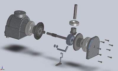
| Exploded view, it is upside down in relation to the images above |
Obviously this is the design we went with given the amount of detail. the 11 gears were traded for 3, with a simple shifting slidegear in between 2 large miter gears. All the gears in this assmebly run constantly but only one (or neither for neutral) are put to use in the output shaft.
*This design has come together over the past week and a half
Simple, light, EXPENSIVE. These gears are 2000 bucks a piece. I could get a new Jeep for the price of this gearbox, so we are still in the process of finding a cheaper vendor and considering machining our own gears.
Welcome to NCSU MAE.


No comments:
Post a Comment